


ACW
Connector for Curtain Wall
This connector was developed to be used with timber curtain wall on concrete floor. It can be used in several configuration depending on the installation. Its special shape allows it to take important load without any deformation.
Označení CE
ETA
Servisní třída 2
Uvnitř
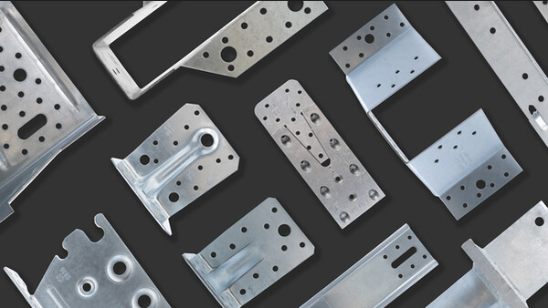
Pozinkovaná ocel Z275
EPD

Podrobnosti produktu
Obrázky


Bracket above. Load direction: F5 = 5 kN

Bracket below, in the middle of concrete

Brackets set below, on slab edge
Vlastnosti
Technické údaje
Rozměry

Rozměry a typické hodnoty

| Art. nr. | Rozměry a typické hodnoty [mm] | Příruba A | Hlava | Box Quantity | Hmotnost [kg] | ||||||
|---|---|---|---|---|---|---|---|---|---|---|---|
| A | B | C | t | Ø5 | Ø9 | Ø13x30 | Ø14 | Ø13x30 | |||
| ACW155 | 154 | 123 | 150 | 2.5 | 33 | 2 | 3 | 4 | 2 | 6 | 1.3 |
Characteristic capacities - Timber to rigid support - Middle of concrete


| Art. nr. | Product capacities - Timber to Concrete | |||||||
|---|---|---|---|---|---|---|---|---|
| Upevňovací prvky | Characteristic capacities - Timber C24 - Middle of concrete [kN] | |||||||
| Příruba A | Hlava | R1.k | R2.k = R3.k | R4.k | R5.k | |||
| Množství | Typ | Množství | Typ | CNA4.0x35 | CNA4.0x35 | CNA4.0x35 | CNA4.0x35 | |
| ACW155 | 13 | CNA4.0x35 | 2 | Ø12 | 16.3 | 15.3 | 21.1 | 5 |
Please note that the loads given in this table are maximum loads. If the anchors don't resist to these loads, they will be reduced.
These capacities are valid with anchors in holes close to the bend
The capacities are given for timber element that can't rotate.
Characteristic capacities - Timber to rigid support - Near concrete edge


| Art. nr. | Product capacities - Timber to Concrete | ||||||||
|---|---|---|---|---|---|---|---|---|---|
| Upevňovací prvky | Characteristic capacities - Timber C24 - Near concrete edge [kN] | ||||||||
| Příruba A | Hlava | R1.k | R2.k = R3.k | R4.k | R5.k | R6.k | |||
| Množství | Typ | Množství | Typ | CNA4.0x35 | CNA4.0x35 | CNA4.0x35 | CNA4.0x35 | CNA4.0x35 | |
| ACW155 | 13 | CNA4.0x35 | 2 | Ø12 | 8.8 | 8.9 | 6 | 11.4 | 21.2 |
Please note that the loads given in this table are maximum loads. If the anchors don't resist to these loads, they will be reduced.
These capacities are valid with anchors in holes far from the bend
Instalace
Instalace

Load direction - middle of concrete slab

Load directions - near concrete edge

Load directions - near concrete edge

Load directions - middle of concrete slab
Bracket above. Load direction: F5 = 5 kN
Bracket below, in the middle of concrete
Brackets set below, on slab edge

ACW - Nailing pattern on CLT wall


